(!)Due to Microsoft's end of support for Internet Explorer 11 on 15/06/2022, this site does not support the recommended environment.
Mon. - Fri. 8 a.m. - 6 p.m.
All Categories
Categories
- Automation Components
- Linear Motion
- Rotary Motion
- Connecting Parts
- Rotary Power Transmission
- Motors
- Conveyors & Material Handling
- Locating, Positioning, Jigs & Fixtures
- Inspection
- Sensors, Switches
- Pneumatics, Hydraulics
- Vacuum Components
- Hydraulic Equipment
- Spray Equipment And Accessories
- Pipe, Tubes, Hoses & Fittings
- Modules, Units
- Heaters, Temperature Control
- Aluminum Extrusions, Framing, Support & Posts
- Casters, Leveling Mounts, Posts
- Doors, Cabinet Hardware
- Springs, Shock Absorbers
- Adjustment/Fastening Components, Pins, Magnets
- Antivibration, Soundproofing Materials, Safety Products
- Fasteners
- Materials
- Wiring Components
- LAN Cables / Industrial Network Cables
- Equipment Specific Cables
- Cordsets
- Computer & AV Cables
- Wire/Cable
- Connector (General Purpose)
- Crimp Terminal Components
- Cable Organization
- Cable Gland Components
- Cable Bushing/Clip/Sticker
- Screw/Spacer
- Cable accessories
- Tube
- Electrical Conduits
- Duct/Wiring
- Electrical Wiring Tools
- Dedicated tools
- Soldering supplies
- Electrical & Controls
- Cutting Tools
- Carbide End Mill
- HSS End Mill
- Concrete Drill Bits
- Milling Cutter Insert / Holder
- Core Drill Bits
- Customized Straight Blade End Mill
- Dedicated Cutter
- Crinkey Cutters
- Turning Tool
- Drill
- Cutting Tool Accessories
- Screw Hole Related Tools
- Reamer
- Electric Drill Bits
- Chamfering, Centering Tool
- Hole Saws
- Magnetic Drill Press Cutters
- Step Drills
- Wood Drills & Cutters
- Processing Tools
- packing & logistics storage supplies
- Safety Products
- research and development & cleanroom supplies
- Press Die Components
- Plastic Mold Components
- Ejector Pins
- Sleeves, Center Pins
- Core Pins
- Sprue bushings, Gates, and other components
- Date Mark Inserts, Recycle Mark Inserts, Pins with Gas Vent
- Undercut, Plates
- Leader Components, Components for Ejector Space
- Mold Opening Controllers
- Cooling or Heating Components
- Accessories, Others
- Components of Large Mold, Die Casting
- Injection Molding Components
- Purging Agent
- Injection Molding Machine Products
- Accessories of Equipment
- Auxiliary Equipment
- Air Nippers
- Air Cylinders
- Air Chuck for Runner
- Chuck Board Components
- Frames
- Suction Components
- Parallel Air Chuck
- Special Air Chuck
- Mold Maintenance
- Heating Items
- Heat Insulation Sheets
- Couplers, Plugs, One-touch Joints
- Tubes, Hoses, Peripheral Components
Applications
Brands
- Webcode Seach | Series
-
#CODE
- Discontinued Products
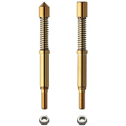
Integrated Probe Assembly - Threaded, MNP50 Series
Click this image to zoom it.
Move the mouse over the image to zoom
- Volume Discount
No soldering is required, because round crimp terminals and round lead wires are tucked in the threads and are secured with nuts.
- inCAD Components

Part Number
Configured Part Number is shown.

| No. | Part | [ M ]Material | [ S ]Surface Treatment |
| ① | Plunger | W1-9 Tool Steel | Gold Plating on Nickel Undercoat |
| ② | Spring | SWP | Gold Plating |
| ③ | Sleeve | Brass | Gold Plating on Nickel Undercoat |
| ④ | Collar | Brass | Nickel Plating |
| ⑤ | Nut | Stainless Steel | - |
Specifications
| Part Number | - | Tip Shape |
| GNP12 FNP10N FNP13 MNP50 | - - - - | G E15 A G8 |
| Part Number | Mounting Pitch (min.) | Full Stroke | Spring Pressure | Allowable Current | Resistance | Replacement Cycle (Reference) | Mounting Hole for Press-Fitting Dimension (Reference) | |
| Initial | 2/3 Stroke | |||||||
| GNP6 | 0.8mm | 3.4mm | 26gf | 80gf | 0.5A | 50mΩ | 100,000 times | 0.48~0.5mm |
| GNP8 | 1.0mm | 3.4mm | 23gf | 80gf | 1A | 0.58~0.6mm | ||
| GNP12 | 1.5mm | 4.0mm | 32gf | 95gf | 3A | 300,000 times | 1.03~1.05mm | |
| FNP10 | 3.0mm (6.0mm) | 4.5mm | 60gf | 105gf | 3A | 80mΩ | 300,000 times | M2x0.25 |
| FNP10N (with Nut) | ||||||||
| FNP10HDN (with Nut) | 56gf | 175gf | ||||||
| FNP13 | 5.0mm (7.0mm) | 4.0mm | 60gf | 100gf | 3A | 80mΩ | 300,000 times | M2.5x0.35 |
| FNP13N (with Nut) | ||||||||
| FNP13HDN (with Nut) | 58gf | 175gf | ||||||
| FNP22SF | 3.0mm | 7.0mm | 0gf | 100gf | 3A | 80mΩ | 300,000 times | 1.98~2.00mm |
| FNP22 | 150gf | |||||||
| FNP40SF | 5.0mm | 17.0mm* | 0gf | 220gf | 3.48~3.50mm | |||
| FNP40 | 300gf | |||||||
| FNPS22 | 3.0mm | 8.0mm | 51gf | 180gf | 3A | 80mΩ | 300,000 times | 1.98~2.00mm |
| FNPS35 | 4.0mm | 8.0mm | 66gf | 200gf | 3.17~3.19mm | |||
| MNP50 | 7.0mm<9.0mm> | 7.6mm | 228gf | 455gf | 5A | 35mΩ | 300,000 times | 4.18~4.2mm |
[ ! ]For orders larger than indicated quantity, please request a quotation.
Part Number
CAD Data download and 3D preview are not available because the part number has not yet been determined.
- *In order to open the CAD Data download and 3D preview screen, the part number must be fixed.
- Please confirm the part number from "Specification / Dimension"on the left side, and then perform the CAD Data Download / 3D Preview operation.
| Part Number |
|---|
| MNP50-A |
| MNP50-B |
| MNP50-C |
| MNP50-G |
| MNP50-G8 |
| MNP50-J |
Loading...
Example

Basic Information
| Type | Contact Probes Assemblies | Minimum Mounting Pitch(mm) | 3.50-9.00 | Full Stroke (Range)(mm) | 7~9.5 |
|---|---|---|---|---|---|
| Full Stroke(mm) | 7.6 | Spring Pressure @2/3 Stroke(Range)(gf) | 300.1 or More | Plunger Material | W1-9 Tool Steel |
| Plunger Surface Treatment | Nickel Plating Backing Gold Plating Finish | Plunger Length L1 (Range)(mm) | 15.1 or More | Integrated Probe Type | Screw Connection Type |
| Receptacle Max. O.D. D (Range)(Ø) | 3.01 or More | Barrel, Receptacle Material | Brass | Barrel, Receptacles Outside Diameter(Ø) | 4.2 |
| Barrel, Receptacle Length L2 (Range)(mm) | 10.1~15 | Properties | Standard | Initial Spring Pressure (Range)(gf) | 200.1 or More |
| Allowable Current(A) | 5 | Resistance(mΩ) | 35 | Plunger Length(mm) | 22.0 |
| Receptacle Outermost diameter(Ø) | 5.0 | Barrel, Receptacles Length(mm) | 15.0 | Initial Spring Pressure(gf) | 228 |
| 2/3 Stroke Spring Pressure(gf) | 455 |
- The specifications and dimensions of some parts may not be fully covered. For exact details, refer to manufacturer catalogs .
Additional Products in this Category
- Contact Probes/Receptacles - 38 Series
- Contact Probes/Receptacles - 68S3 Series
- Contact Probes/Receptacles - 88 Series
- Receptacles with Lead Wire - for 45, 88 Series
- Contact Probes/Receptacles - 89 Series
- Integrated Probe Assembly - Standard
- Circuit Board Rough Guides
- Double Tipped Probes
Complementary Products
-
 Proximity Sensor Accessories - Disc Sensor, with Slit, with Set Screw
MISUMI Days to Ship : Same day or more
-
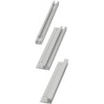 Rails for Switches and Sensors - Aluminum with Scale, L Dimension Configurable
MISUMI Days to Ship : 9 Days or more


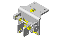
MISUMI Unit Example related to this product

Tech Support
- Technical Support
- Tel:+52-442-672-7661 ext. 2 then wait and dial 4
E-mail: soportetecnico@misumimex.com - Mon. - Fri. 8 a.m. - 6 p.m.
- Technical Inquiry
How can we improve?
How can we improve?
While we are not able to respond directly to comments submitted in this form, the information will be reviewed for future improvement.
Customer Privacy Policy
Thank you for your cooperation.
While we are not able to respond directly to comments submitted in this form, the information will be reviewed for future improvement.
Please use the inquiry form.
Customer Privacy Policy